OSO Analog Synthesis Tutorial (Part 1)

Modular Synthesizers Basics
With Behringer recently announcing their entering in the modular synths market too, we have a clear confirmation that this sector is very active, people want to play more with experimental setups, the interest for modular synthesis is still high and will increase even more, due to a future reduction in the costs.
This OSO tutorial will give you a simple guide on how to move your first steps on the analog synthesis and how to deal with basic modular setups.
Doesn’t the idea of creating your own sounds from scratch stimulate you, turning the foundations on which your music is built, unique?
This tutorial is dedicated to musicians and producers who already use analog synthesizers even in their virtual form, but hadn’t the opportunity to study their structure, how they work and the basics of sound design.
To make things simple, we tried to condensate some basics notions we believe are important to know, leaving out the theory and complicated concepts. The idea is to share some basic knowledge to understand how sounds are made and start building some basic modular synth configurations, with the help of the open-source DAW, vcvrack, ideal for experimenting with the first steps in sound editing and feeling perfectly at ease when one day the chance to play with an authentic analog beast will come.
SCARY MONSTERS
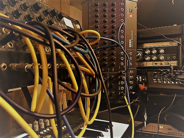
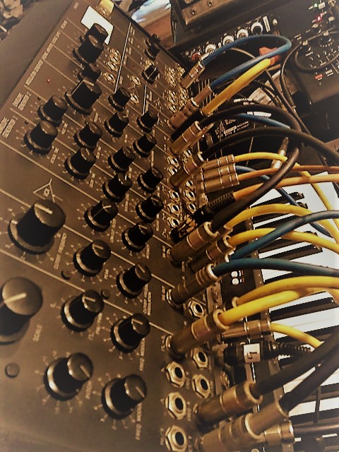
I remember, while a youth, being ecstatic every time I watched Keith Emerson on television; that huge closet full of cables and buttons capable of those strange sounds, never listened before, was incredibly attractive to me. It seemed impossible to be able to disentangle between huge masses of cables and buttons as if these instruments were only within the reach of mad scientists and sure provided with huge budgets.
Born by assembling laboratory tools, the first synths were made of pre-built modules combined between them through connectors and patch cables, perfect for the studio but not as great for the stage. As technology was revolutionizing music, a need for new sounds and instruments easy to carry, soon developed. Manufacturers started building pre-patched, already configured devices, much easier to transport and to program. These have dominated the market for long, successful synths like the Minimoog, the ARP Odyssey or the Roland SH and Yamaha CS series are perfect examples.
After 50 years it is rather curious to see how the complex modular synths, requiring a long process of setup and without any recall function, not only survived but instead are becoming increasingly popular. It is now possible to buy everything, from small modular synths that cost as much as a mobile phone, to perfect copies of the modular Moog synths of the 70s.
Even in their virtual form, the interest is so high that over the years, in addition to various commercial programs, an open-source program has been developed, very rich in modules, sounding really good and completely free: vcvrack, modeled after the Eurorack modular synth standard. This program seems to me ideal to start experimenting with the structure of modular synthesizers, to become familiar with the modular format in order to decide one day whether to switch to a real instrument or not. Personally, although I love all kinds of synths, I’m particularly fascinated by the pre-configured vintage ones, mostly for their historical value. My only modular is the old Korg MS-50, a fairly rare tool, that being small and simple to use, will be definitely used for this tutorial, along with vcvrack and Propellerhead Reason.
THE STRUCTURE OF SOUND
Surviving Tool
Sounds are nothing more than perturbations in the status of the AIR, where Silence means no movement of it at all. Once the air is moved by an object, vibrations in a particular range of frequencies are read by our sensors and processed by the brain as sounds.
Without ears as capturing devices and the brain as our CPU to process the vibrations, there wouldn’t be any sound.
Sound is, therefore, a living beings’ construction, surely developed for surviving purposes.
WAVEFORMS
Being based on electronic circuits and mathematical functions, synths started implementing basic sound waves, slowly increasing their complexity up to today’s super-rich waveforms obtained through implementing different forms of synthesis together.
The basic shapes available in a typical classic synth Oscillator are the following and their names describe their physical shapes:
–Sine Wave: This is the most basic wave, where frequency and amplitude increase and decrease in the same way, Smooth sound, not too “exciting” if listened alone.
–Triangular: Similar to a Sine but sounding a bit brighter.
–Sawtooth: Rich and sharp sounding, one of the most common waveforms in classic synthesizer sounds.
–Square: The richest in harmonics, it sounds like a distorted lead guitar.
Adjusting its width through a Pulse Width control allows great sound variation.
–PWM: Rich modulated waveform, obtained modulating the voltage of a Square waveform’s pulse width.
Sine Waves Interacting
Any complex sound can be reduced to chains of sine waves of different amplitudes varying in time (Envelope) and in Frequency.
Additive Synthesis (see later) as well as the Fourier mathematics theory that brought to the development of the FFT (Fast Fourier Transform) algorithms needed for our DAWs, is based on this concept.
Spectrograms.
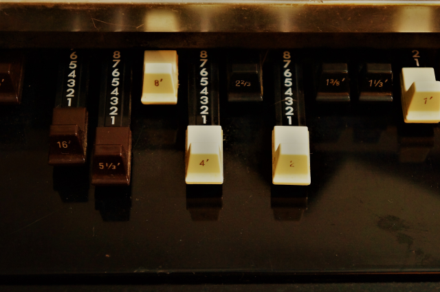
Complex sounds are the sum of multiple sine waves of a base frequency, called Fundamental (L). The Second (1/2L), Third(2/3L), Fourth (1/2L), etc. Harmonics or Overtones are all multiples of this base frequency. Synths are the only instruments capable of creating pure tones, without any harmonics.
Depending on how the air is moved, we can recognize three basic aspects of the sound:
Volume and its variation in time or duration
Tuning (the fundamental’s frequency)
Tone (harmonic content).
Volume
or Amplitude depends on the power of the vibration, or the pressure that reaches our sensors and is measured in Decibels (dB).
Dynamic Range is the relation between the sound and the background noise (variable depending on the situation).
Here a few examples of the range possible:
- At night outside in the fields, about 20dB,
- in the center of a city, about 50dB,
- a concert piano should reach around 94dB
- the maximum tolerated pressure before pain is 130dB
In HiFi and other electronic devices, you can often find negative dB values. These refer to the amount of dB available starting from the highest volume possible, being 0 dB the distortion point.
Pitch
Our sensors are able to identify when cyclic patterns are present in the sound we hear. These, if inside the human perception range of 20Hz to 20.000Hz (variable by subject and age) are read by the brain as a Periodic sound. The speed of the cyclic movement determines the Pitch of the sound, that at this point can be called a Note.
Our perception of sound differs with Frequency:
Ears are especially sensible in the range between 1000 and 3000Hz, the frequencies mostly used for communication. It is interesting to take a look at the Fletcher-Munson Curves of Isofony to understand that low frequencies are perceived well, only when they reach a certain level of volume.

By Lindosland at en.wikipedia – this image created by lindosland Dec 2005 using OpenOffice Draw., Public Domain, Link
If you are aged enough you will certainly remember the “Loudness” switch on the old HiFi gear, to use when listening to music at low levels. Remembering this aspect when in front of the speakers can be very useful when determining the right amount of low end for the mix, while mixing.
Tone
A bit more difficult to explain, this is the “factor” that permits to recognize an instrument from another even when they are playing the same note. Every instrument sound and the way that the performer plays it make a sort of sound DNA. If the sound is analyzed in its basic components, how the Overtones change in time is the key factor that has a great impact on recognizing the “Character” of the sound.
PHASE How the overtones interact between them depends on their Phase too. Waves crossing in counter-phase will CANCEL, abruptly stopping the vibration of that precise frequency and altering the sound’s shape.
ADDITIVE SYNTHESIS
As we have seen before, complex sounds can be reproduced by summing several basic sinusoid waves. Additive Synthesis is based on this concept and we can consider Pipe, Hammond, and Electronic Organs as the first Additive Synthesizers, as each part they use to generate a complex sound is constituted by an oscillator producing more or less a sine wave. While additive synthesis looks like a brilliant idea, the technology needed to produce rich dynamic sounds with sharp transients, has become available only in “digital times”. In nature, percussive sounds change very fast their harmonic content, especially in the attack transients. Even having various oscillators playing at the same time, only varying their individual levels in an organized form can reproduce well these sounds’ character.
The synth’s architecture complexity needed to do so starts becoming evident: It would require each Oscillator/Sine Wave to have its own amplification and Envelope control, making the circuit very complex and expensive. This possibility became practical only in digital times especially with FM synthesis, where each operator had its own envelope emulating this way the complex overtones patterns of instruments of percussive nature.
For reasons of complexity, in analog times, only very few manufacturers applied this technology deeply. Organ makers being forced to turn their production towards the new technology, implemented in their synths some basic additive synthesis directly taken from their organ circuits (Divide-Down architecture), as the Italian Crumar or Farfisa for their “Polyphonic Section“.
SUBTRACTIVE SYNTHESIS
The concept behind Subractive is exactly subtracting through filters and envelope control a static basic wave, to obtain a great variety of sounds.
“VOLTAGE CONTROL” = The Synthesizers’ Language
Before MIDI appeared, synthesizers were played through the combination of two different signals:
– A variable DC voltage to control for example the height of the note, often in the range between -/+ 3 and -/+15 volts, where each note had its own fixed value, being 0 volts the central note of the keyboard.
– A “switch” to detect the action of pressing the keyboard. Being synths monophonic, all keys acted on this same “switch”
The CV or Control Voltage
Typically the frequency or note of a sound played with an analog synth keyboard is determined by the Voltage of the key pressed, following two different formats:
Volts per Octave (Voltages increase one Volt per octave)
Voltages increase (or decrease) constantly, every increase/decrease in octave corresponds to more or less a Volt.
Hertz per Volt (Voltages double at each octave up)
Used mainly on Korg and Yamaha synths, the voltage doubles when you play an octave higher. Same as what happens to the frequency in Hertz that doubles for each increase of an octave, the same happens to voltages.
GATE or Trig
At the same time, the triggering of the note is made through the variation of voltage when pressing a key of the keyboard or a switch, again in two different forms:
V-Trig: the note is activated by the voltage emitted by the key/switch when pressed, it is called GATE too.
S-Trig: A single pulse capable of activating a function, made through shortening a continuous voltage
DIN Sync or Sync24: This is the pre-MIDI standard for Synchronization of tempo between analog devices. For the tracking, it used trains of signal pulses (Roland used 24 per Quarter Nore) The connectors are similar to MIDI but, depending on the manufacturer, can use up to all the five pins.
SYNTHESIZER MODULES
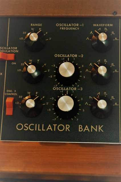
Oscillators
These are devices that reproduce electrically what happens in nature, creating a pulse in the audio signal, an “oscillation” within a specific range that corresponds to the audible window. The higher the frequency of oscillation, the higher the pitch of the sound.
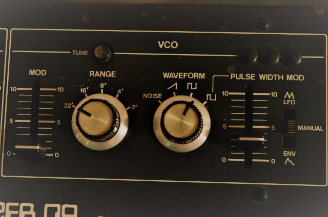
VCO = Voltage Controlled Oscillator
VCO stays for voltage controlled oscillator, this means that the amount of voltage fed to their input changes the pitch of the waveform.
If the oscillator is set to vibrate at frequencies below the audible range, the VCO becomes an LFO, Low-Frequency Oscillator. These are used to “modulate” a sound in different forms, “perturbating” the normal pitch, volume or stereo balance, for example.
VCF = Voltage Controlled Filter
In Subtractive Synthesis, huge importance takes the
FILTER, responsible for altering the spectral shape of the oscillator’s waveform. Between the various forms of filtering, it is important to mention the LPF Low Pass Filter, where only the low frequencies can “pass” through it or its opposite, the HPF High Pass Filter, but sometimes Band Pass are used too and in modern designs, any possible filter configuration.
Filters can be distinguished by the way they cut frequencies out, like 12dB/Octave or 24dB/Octave.
Their main controls are two: CUTOFF frequency that corresponds to the “tuning” or the filter, or in which frequency its action is centered and the RESONANCE is the gain applied to the Cutoff Frequency, in the higher setting can generate an Auto-Oscillation, an additional tone which pitch can be adjusted by the Cutoff Frequency.
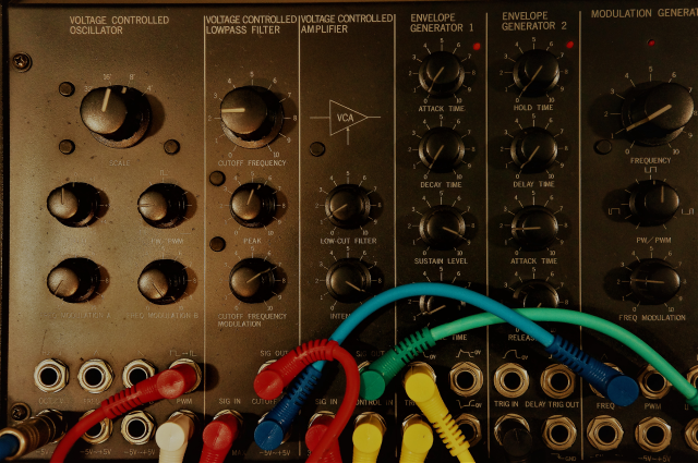
VCA = Voltage Controlled Amplifier
The VCA, constituted by a controlled amplification stage, takes care of the gain of the signal and is controlled by the GATE signal we mentioned before. The gain is usually controlled by the Envelope, normally in the form of an ADSR, this name staying for Attack, Decay, Sustain and Release, explaining pretty well their action on the signal.
Patching
Pre-Patched, Patchbays and Matrix
Analog synthesizers started as various laboratory modules connected together through patches, all points of access of their functions were usually connected to a Patchbay or a MATRIX a more specialized version of it. When mass production of synths started, selling already pre-patched configuration synths, easy to use and transport, made these instruments so popular.
NOISE Having an important rule in reproducing the sounds of nature, a noise source started being implemented very soon, already mixed in preset configurations or often as a separate section, like one specialized oscillator more. White noise has all frequency spectrum occupied, the other “colors” (Pink, Red, Brown…) refer to the shape of the spectrum having more high or low frequencies involved.
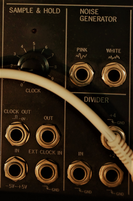
S&H Sample & Hold, this has always been one of the more “obscure” functions of analog synths, not exactly intuitive. This function “captures” a moment in a CV fluctuation of a source like an LFO sweep and holds this value until a new event arrives, quantizing the signal in steps. Random notes or wobbling filters are obtained through this function.
A classic example is the Moog III in Emerson, Lake & Palmer, Karn Evil 9 1st Impression, Pt. 2 (Welcome Back My Friends), where the sample and hold function is applied to the Filter Cutoff of the Moog modular. We will return to this patch in the practical examples.
RING MODULATOR In this module, two signals are “multiplied”. The sum or subtraction of frequencies due to Cancelation generates a completely new shape in the waveform. The resulting rich sound is ideal for recreating percussive metallic sounds.
VCVRACK SETUP
Let’s take a look at vcvrack and try to experiment with modules connections:
All connectors with a black label are sources. When dragging from a jack of a module to another to connect them, incompatible inputs are greyed out.
Once the program is installed, open a New File. The default patch is a pre-configured basic modular synthesizer. On the AUDIO-8 module, you can select the audio driver, outputs, sample rate, and audio buffer.
To make things simpler to understand, let’s remove a few modules doing right-click and delete, like Notes, ADSR, and VCF.
VCO in action
If we now connect the VCO output to the MIXER IN 1 input, we can start listening to its voice.
The waveforms available are four: Sine, Triangular, Sawtooth, and Square. Let’s connect the SIN output to the MIXER Input 1, here we have it visible in its shape on the included SCOPE screen. While beautiful to see if listened alone, this waveform is the most boring and unattractive available sound. It is extremely important in testing electronics but not too musical, as the perception of its pitch is made difficult by its loss of harmonics. Furthermore, the same shape can be easily obtained with other waveforms passed through an LPF.
The TRI stays for Triangle, a richer sounding waveform, SAWtooth has an even sharper sound and SQR for Square is the more full sounding, pretty similar to a distorted guitar. This last waveform has an important function, its width can be varied through a potentiometer called PULSE WIDTH, the variation of this parameter while playing a Square, is very pleasant and interesting. It is possible to patch an LFO to automize this process and get a rhythmic variation, for example.
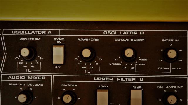
SYNC
Old analog synths had problems in maintaining the pitch of the oscillators stable. While with only one oscillator the problem could easily be fixed with a tuning knob, having two or more oscillators, created some serious problems. A simple change in the voltage (the power supplies weren’t as stable as today), or even in the temperature of the space around the synth, brought to a detuning of each oscillator in its own way, a total mess if playing live. To avoid this SYNC was introduced, this is a process consisted of slaving the oscillators to a “master” one, resetting the slaved waveform every time it passes through the 0 amplitude, to force to maintain the frequency of the master. Once synced a rich phasing sound is obtained moving the FREQ knob of the slave or master oscillator.
VCF in Action
Let’s add the VCF module we had removed at the beginning.
Patching our oscillator through a Voltage Controlled Filter permits to benefit of the great modification capabilities the filter is capable of.
The VCF mode available on the vcvrack virtual modular is of two kinds, LPF or HPF. Let’s connect the TRIangle waveform output with the VCF IN and the LPF OUT with MIXER IN-1. Acting on the FREQ knob, we can alter the frequency where our Filter works. The action of this knob can be controlled with a CV, sending voltages to the FREQ jack.
Auto-oscillation
Acting on the RESonance knob, we can increase the GAIN of the range of frequencies the filter is affecting, up to a point that the filter starts acting like an oscillator. This can be extremely useful as a source more for complex sounds or for special effects.
VCA in Action
This module name can be pretty familiar to those who have previous experiences with hardware audio dynamic processors, as VCAs are implemented on various popular compressors designs, like DBX or SSL.
An amplifier is controlled through a CV input, at more voltages are feed, more gain results. Many times the same module offers control of the ADSR where the dynamics of the sound can be controlled easily.
ADSR or Envelope Generator
This module generates a variation of voltages in time. It needs a triggering from an external source, like the TRIG signal, to start its action.
A for Attack means the TIME a sound takes to reach its maximum level. It can be raised to reproduce the slow attack of a string section or at its minimum value for a percussive sound.
D for Decay determines the TIME sound takes to fall to the level set by the Sustain level.
S staying for Sustain is the residual LEVEL while you still have the keyboard’s key pressed. To reproduce, for example, an organ sound, this value should be set at its maximum.
R for Release is relative to the TIME the sound takes to fade completely off, large values can give the illusion of a reverb effect.
In the next post, we will try some practical examples, stay tuned!

5 Comments
Spiralizer · December 22, 2019 at 11:37 am
Cool article Max! I for one have my eye set on the forthcoming Behringer ARP2600 clone – just when I’d promised myself they weren’t getting any more of my money lol!
max · December 26, 2019 at 3:29 pm
I’m glad you enjoyed the tutorial!
I’m a big fan of Joe Zawinul, I’ve been loving the 2600 since I was a boy!
If buying an affordable clone would become a reality, I would immediately fall into a heavy GAS!:D
rick · December 22, 2019 at 3:45 pm
awesome info
max · December 26, 2019 at 3:09 pm
Many thanks Rick!!
OSO, original sounds only, Modular SYnths TUTORIAL | maxpro.audio · January 9, 2020 at 6:10 am
[…] OSO Analog Synthesis Tutorial (Part 1) AnalogCV GateEurorackmodular synthesizerSynthTutorialvcvrackVoltage Control […]